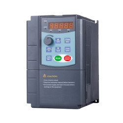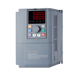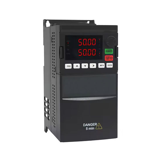
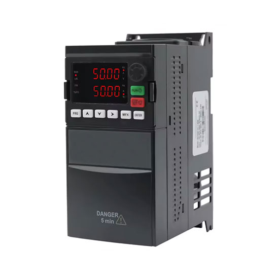
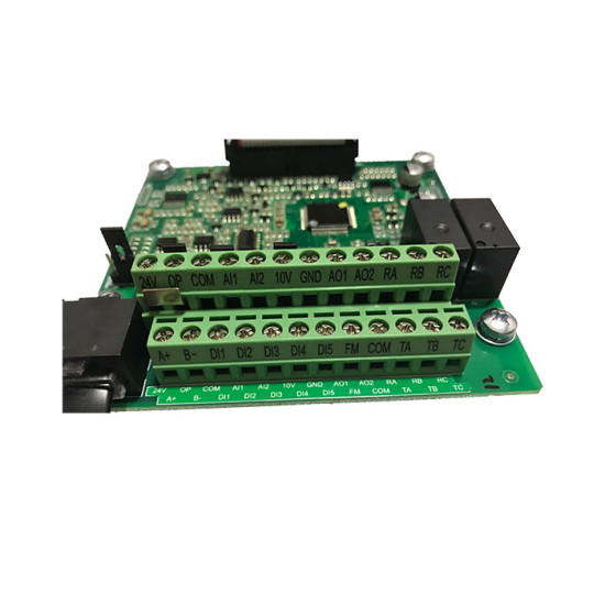


- Stock: In Stock
- Model: PEACO-FC100P-4T-0.7GB
Available Options
1 hp VFD with 3-phase features input and output 220/240/380/400/415/440/460/480V, full protection such as overload, over-heat, etc. The AC drive supports open-loop vector control (SVC) and the V/f control method for better performance. Peaco Support VFD is a cost-efficient motor controller drive to control the motor.
Technical Specifications
| Basic Features | Model | PEACO-FC100P-4T-0.7GB |
| Code | G: Constant torque and P: Pump motor | |
| Rated capacity | 1 hp (0.75kW) | |
| Rated input current | 8.2A(200V~240V), 3.4A(380~480V) | |
| Rated output current | 4.0A(200V~240V), 2.1A(380~480V) | |
| Input/output rated voltage* | 220V,240V,380V,440V,460V and 480V | |
| Input rated frequency | 50/60Hz | |
| Output frequency | Vector control: 0~300 Hz, V/F control: 0~500 Hz | |
| Adoptable motor type* | Squirrel cage induction motor, asynchronous motor (Contact us for Permanent Magnet Motor) | |
| Control Features | Control mode | Open-loop vector control (SVC) and V/f control |
| Speed setting resolution | Digital setting: 0.01 Hz, Analog setting 1%*maximum frequency | |
| Speed setting method | Digital setting/pulse setting, communication setting | |
| Torque control response | <200ms (SVC) | |
| Start-up torque | 150% rated torque/0.5Hz (SVC) | |
| Overload capacity | 150% rated current 60s, 180% rated current 2s | |
| PID adjustment function | Built-in process PID module | |
| Simple PLC function | Built-in simple PLC module, which can realize timing and multi-segment frequency output | |
| Individualized and safety function | Overvoltage stall | Bus voltage automatic control to prevent overvoltage faults |
| Automatic current limiting protection | Output current is automatically limited to prevent over-current faults | |
| Overload pre-alarm | Overload early warning and protection | |
| Input and output phase loss protection | Input and output phase loss automatic detection and alarm function | |
| Overvoltage and overflow stall control | Automatically limit the current and voltage during operation to prevent frequent over-current and over-voltage trips | |
| Output short-to-ground protection | Output to ground short-circuit effective protection function | |
| Output phase-to-phase short circuit protection | Output interphase short circuit effective protection function | |
| Textile wobble control |
Built-in textile swing frequency function module |
|
| Water supply function | Built-in constant pressure water supply parameter macro | |
| Engraving machine function | Built-in engraving machine high-frequency parameter macro | |
| Fire mode | Built-in European fire mode parameter group | |
| Running command sources | Running command sources | Three channels: operation panel, control terminal, and serial communication port. They can be switched over between these sources in various ways. |
| Frequency sources | Digital setting, analog voltage setting, analog current setting, pulse setting, serial communication port setting, etc. They can be switched over these sources in various ways. | |
| Relay output and MODBUS communication | TA/TB/TC and RA/RB/RC: Contact capacity 250VAC/3A or 30VDC/1A, RS485 communication mode (A+, B-) | |
| Input terminal | 5-Digital Input terminal, where DI5 is compatible with high-speed pulse input | |
| 2-Analog Input terminal 0-10V/0-20mA. Used either voltage or current input. | ||
| Output terminal | 2-Digital output terminals A02 and FM. | |
| FM can be selected as high-frequency pulse signal output and AO2 can be selected as digital output signal or analog output signal. | ||
| 2-Analog output terminal. AO1 is used either as voltage or current output and AO2 is used for voltage output 0-10V when not functioning as a digital output signal. | ||
| Display and keyboard | LED display | 5-digit double LED digital tube, set frequency, output frequency, output voltage, output current, motor speed, output torque, digital terminals, status parameters, programming menu parameters and fault codes, etc |
| Indicator light | 3-unit indicators, 4-status indicators | |
| Protection function | Short circuit detection, input and output phase loss protection, overcurrent protection, overvoltage protection, under-voltage protection, overheat protection, and overload protection. | |
| Brake unit | Build-in brake unit | |
| Environment | Installation location | Indoor, free from direct sunlight, dust-free, corrosive gases, combustible gases, oil smoke, vapor, dripping water or salt, etc. |
| Altitude | <1000m, derating is required for more than 1000m | |
| Ambient temperature | -10°C~ +40°C (ambient temperature is 40°C-50°C, please de-rate use: output current derated by 2% for every 1°C) | |
| Humidity | < 95 % RH, no water droplet condensation | |
| Vibration | 3.5m/s2 at 2-9Hz | |
| Storage temperature | -40℃~+70℃ | |
| IP level | IP20 | |
| Pollution grade | Class-2 (dry,non-conductive dust pollution) | |
| External Accessories* | Matched optional Brake resistance, input EMC filter, output EMC filter, input AC reactor, output AC reactor, energy regenerated reactor, harmonic filter, and sine wave filter (excluding VFD price). | |
| Certificate | CE, RoHS, and ISO9001 | |
| Warranty | 1 year | |
1. * Denotes the parameters are optional or customized and please select every parameter in drop-down lists to complete your order.
2. Please contact us for the external accessories catalog and close-loop vector control VFD inquiry (PEACO-FC110 series).
3. 1-hp three-phase VFD comes with a built-in brake unit. The customer must install brake resistance along with VFD when rapid deceleration is activated for the motor.
Variable Frequency Drive Wiring Diagram
AC Drive Dimension (Unit: mm)
| W | H | D | W1 | H1 | d | Weight |
| 89.6 | 197.2 | 139 | 74 | 187 | Φ5 | 1.5kg |
KNOWLEDGE BASE --- VFD Working Principle
VFD (variable frequency drive) converts an alternating current (AC) with constant voltage and frequency to an alternating current (AC) power source with adjustable voltage and frequency through switching on/off with an internal IGBT.
The frequency converter mainly adopts the AC-DC-AC method (VVVF frequency conversion or vector control frequency conversion). The industrial frequency AC is converted to DC through the rectifier and then the DC is changed into AC with controllable frequency and voltage to supply the motor.
Variable frequency drive is mainly composed of a rectifier (AC to DC), filtering, inverter (DC to AC), brake unit, drive unit, test unit, and micro-processing unit.
- The first section of VFD (variable voltage control) not only converts the AC supply voltage into DC but also controls the required pulsating DC output voltage to maintain V/f constant ratio by using SCR/IGBT rectifier.
- The second section of VFD (DC-Link/DC Bus) consists of inductance and capacitors to convert pulsating DC into pure direct current. Here, inductance smooths the current, and the capacitor smooths the voltage.
- The third section of VFD (referred to as variable frequency control) not only converts DC voltage back into AC voltage but also controls the variable frequency to maintain the V/f ratio by using electronic devices such as SCR/IGBT transistors.
- Cooling method-forced air.
- Keep away the ac converter from corrosive gasses, liquid, moisture, and dust.
- Installation location altitude below 1000m (In the case above 1000m, VFD is to be de-rated. Please contact for technical support).
- Storage-temperate -20℃ to +60℃.
- Ambient temperature -10℃ to +40℃ (non-condensing and not frozen).
- Ambient humidity below 90% RH.
- Vibration under 20Hz 9.8m/s(1G), over 20Hz 5.88m/s (0.6G).
- V/f (volts per hertz) or V/hz control.
- V/f with encoder or closed loop V/f (PG card).
- Open loop vector control.
- Closed loop vector control (PG card).
- VFD capacity is to be sized more or equal to the sum of the capacity of all connected motors.
- The sum of the distance between the VFD and all connected motors should be less than 500m. Introduce an output load reactor to avoid motor failure due to voltage spikes, current surges, or harmonics.
- Install circuit breaker MCB or with extra protection MPCB between each motor and VFD.
- The voltage of each motor should be the same and ensure the VFD adoptable current is higher than the sum of all rated currents.
- Connect all motors with VFD output in parallel.


