

- Stock: In Stock
- Model: PEACO-FC280-2S/4T-0.37G/0.75P
- SKU: PEACO-STVFD-1-2
Available Options
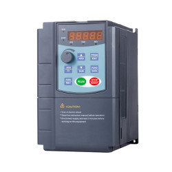
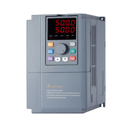
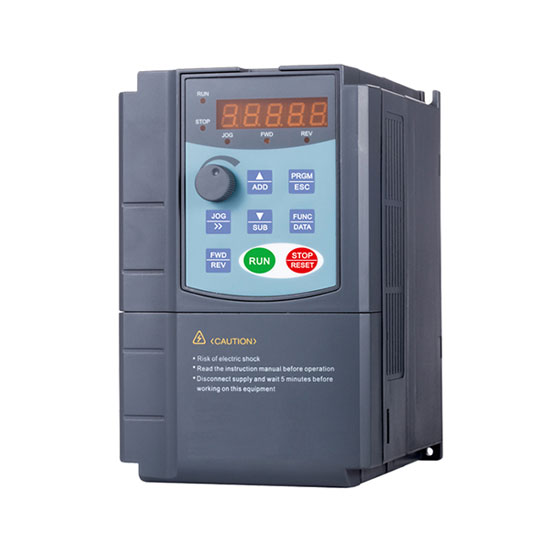
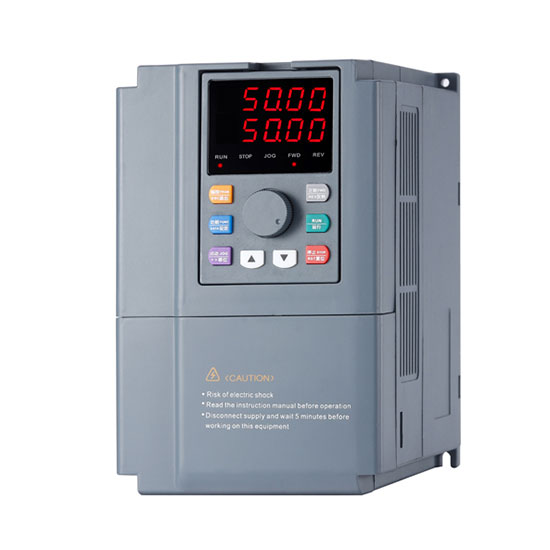
1/2 hp VFD for general purpose converts single phase to three phase, controls the speed, torque and direction of AC induction motors, 1.7 amps rated input current, 220V to 240V variable speed drive, RS485 communication port, widely used in conveyors, fans, pumps, directly supplied from factory.
Our VFD are suitable for single phase and split phase input power supply.
Navigation: Motor Controls > Variable Frequency Drives >1 Phase to 3 Phase VFD > 1/2 hp VFD, Single Phase to Three Phase
Specifications
| Basics | Model | PEACO-FC280-2S/4T-0.37G/0.75P | |
| Rated Capacity | 1/2 hp (0.37 kW) | ||
| Rated Input Current | 1.7A (for 220V) | ||
| Rated Output Current | 1.0A (for 380V) | ||
| Certification | CE | ||
| Warranty | 12 months | ||
| Applicable Motor Output | 0.37 kW (for heavy duty), 0.75 kW (for pump) | ||
| Power | Input Rated Voltage* | 220V±15% |
|
| Output Rated Voltage* | 220V±15%, 380V±15% |
||
| Rated Frequency | 1.0~3200Hz | ||
| Robust Design | IGBT current > 2 times of inverter output current, Capacitor > 50uF/A | ||
| PCB aging test | 100% test, 50°C, 12 hours. | ||
| Finished products aging test | 100% test, 50°C, 24 hours. | ||
| Control Feature | Control System | VF Control / Open Sensor Vector Control / Closed loop Vector (PG card - for lift/elevator) | |
| Output Frequency Resolution | 0.1Hz | ||
| Torque Characteristics | Including the auto-torque, auto-slip compensation, starting torque can be 0.5 Hz/150% (V/f), 1 Hz/150% (SVC),0 Hz/180% (FVC) | ||
| Overload Endurance | 150% / 120s, 160% / 60s, 180% / 10s, 200% / 1s | ||
| Acc / Dec Time | 0.1~65000s. (can be set individually) | ||
| Torque Boost | Automatically torque boost, manually torque boost: 0.1%~30.0% | ||
| Stall Prevention Level | 20~200%, setting of Rated Current | ||
| Operating Feature | Input / Output Terminals | Keypad | Removable |
| Input terminals | 6 multifunctional inputs, one can be work as high speed pulse Input. 3 programmable analog input: AI1, AI2, AI3: 0~10V / 4~20mA. |
||
| Output terminals | 2 Groups relay outputs, 1 open collector outputs. 2 Analog outputs, 0~10V / 4~20mA. |
||
| Communication Terminals | Build-in standard RS485 communication interface. MODBUS-RTU communication protocol. | ||
| Built-in PID | Built-in PID control to easily realize the close loop control of the process parameters (such as pressure, temperature, flow, etc.) | ||
| Jog Operation | Jog operation frequency: 0.0Hz~maximum frequency. Jog acceleration/deceleration time: 0.1s~3600.0s. | ||
| Other Function | AVR, S-curve, Over-Voltage Stall Prevention, DC Braking, Fault Records, Adjustable Carried Frequency, Starting Frequency Setting of DC Braking, Over-Current Stall Prevention, Momentary Power Loss Restart, Reverse Inhibition, Frequency Limits, Parameter Lock/Reset. | ||
| Protection | Over Voltage, Over Current, Under Voltage, Overload, Electronic thermal, Overheating, Self-testing. | ||
| Others | Including EMC Filter (C2/C3 Standard) | ||
| Cooling | Forced air-cooling | ||
| Installation Location | Altitude 1,000 m or below, keep from corrosive gasses, liquid and dust. | ||
| Ambient Temperature | -10°C~+40°C (Non-Condensing and not frozen) | ||
| Storage Temperature | -20°C~+60°C | ||
| Ambient Humidity | Below 90% RH (non-condensing) | ||
| Vibration | 9.80665m/s2 (1G) less than 20Hz, 5.88m/s2 (0.6Gat) 20 to 50Hz | ||
| External Accessories* |
Matched optional input EMC filter, output EMC filter, input AC reactor, output AC reactor, energy regenerated reactor, harmonic filter, sine wave filter (excluding VFD price). |
||
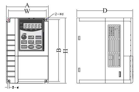
AC Drive Dimension (Unit: mm)
| A | H | D | W | B | Φ | Weight |
| 118 | 185 | 157 | 106 | 175 | Φ4.5 | 2kg |
KNOWLEDGE BASE
Why Does VFD Driven Motor Overheat During Running?
1. The ambient temperature is too high.
Cause: The variable frequency drive inside is composed of countless electronic devices, which will generate a lot of heat when it works, especially the IGBT will generate more heat when it works at high frequency. If the surrounding temperature is too high, the temperature of the internal components of VFD will also be high. The AC drive will report a high temperature signal and stop in order to protect its internal circuit of the AC drive.
Solution: Reduce the temperature of the place where the inverter is located and installing an air-conditioning or additional fan to cool the VFD is also a better solution.
2. Poor ventilation of the inverter.
Cause: If the air duct of the VFD or control cabinet is blocked, it will not only affect the internal heat dissipation of the inverter, but also cause the variable speed drive to overheat and give out an alarm.
Solution: Check and repair the inverter regularly, remove the garbage in the air duct and smooth the air duct.
3. The fan is blocked of VFD or damaged.
Cause: When the inverter fan is broken, a large amount of heat accumulates in frequency converter and cannot be dissipated timely.
Solution: Replace the fan for the frequency converter.
4. The application load of VFD is too high.
Cause: When the application load of VFD is too high, it will generate excessive current and produce a lot of heat. Sometimes the variable frequency drive will set an alarm because of overheat.
Solution: Reduce the load or increase the capacity of the VFD. In general, the inverter capacity should be considered to be 1.8 times of that of load power when we select an variable frequency drive.

