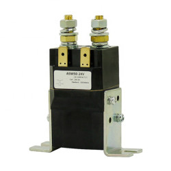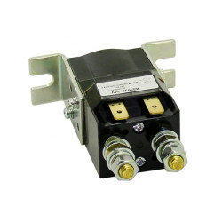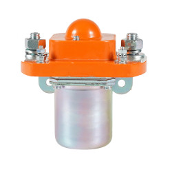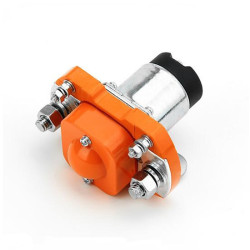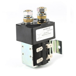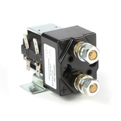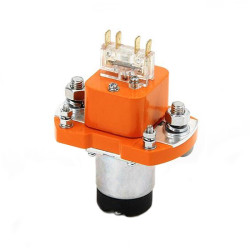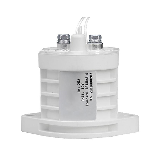
- Stock: In Stock
- Model: PEACO-SJD-30
- SKU: PEACO-SJD-30
Available Options
Features
1. The reliable sealing enables the DC contactor relay to be used in harsh and explosion-proof environments for a long time and its internal components including coils and contacts are not oxidized. The DC contactor also features low energy consumption, low heat generation, long life, small size and light weight.
2. The DC contactor relay can control high voltage and high current.
3. Smaller arcs make the contactor more effective and safer to use. The relay is sealed with inert gas, which ensures that there is basically no arc between the contacts when the contactor is in action and magnetic blow-out is adopted to ensure safety.
4. High stability. The internal mechanism and structure of the contactor are completely sealed with the inert gas, free from the interference of adverse external factors and the contact resistance remains stable for a long time.
5. Wide application. DC contactor relays are widely used for DC power control, battery switch control, circuit safety protection, etc.
6. Lead time: 22~25 days, MOQ: 3 pieces. For similar unit with shorter lead time and MOQ-1, please visit at 30 Amps High Voltage DC Contactor.
Specification
| Model | PEACO-SJD-30 | ||
| Coil | Rated Voltage | 12V DC | 24V DC |
| Working Voltage Range (20℃) | (85%-110%)Us | (85%-110%)Us | |
| Pull-in voltage (20℃) | 75% Us Max. | 75% Us Max. | |
| Maintain voltage (20℃) | 85% Us Min. | 85% Us Min. | |
| Release voltage (20℃) | 10% Us Min | 10% Us Min | |
| Coil resistor (20℃) | 45Ω±5% | 167Ω±5% | |
| Coil power (20℃) | 3.2W | 3.5W | |
| Coil polarity | No | No | |
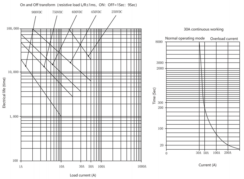
| Main contact | Max. continuouse overcurrent | 30A | |
| Contact voltage | 12-900V DC | ||
| Rated control capacity | 30A 450V DC | ||
| Short-time withstand current | 90A 30S | ||
| 150A 10S | |||
| Contact pull-in time | 25ms max. | ||
| Contact release time | 10ms max. | ||
| Max. breaking current (>1 time) | 300A 350V | ||
| Contact type | 1 set normal open | ||
| Contact polarity | polarity or nonpolarity | ||
| Contact resistor | ≤ 2mΩ | ||
| Life time | Machanical life | 1,000,000 times | |
| Electrical life (L/R ≤1ms) | 10,000 times | ||
| Dielectric properties | Between contacts | 2500V AC/ 60 Sec/1mA | |
| Between contacts and coils | 2500V AC/ 60 Sec/1mA | ||
| Mechanical property | Impact | 20G peak value, 11 ms 1/2 sine wave (coil electric connection) |
|
| Vibration | 20G peak value, 8-2000Hz sine wave | ||
| Working Environment | Environment temperature | -40℃~+85℃ | |
| Humidity | 5%~85% RH | ||
| Altitude | <4000m | ||
| Certification | CE | ||
| Weight | 110g | ||
- Drive and control systems for mining equipment and mechanical vehicles.
- Power control, circuit insulation of industrial machinery.
- DC switch equipment.
- Car battery power distribution and backup.
- Hybrid electric vehicles, electric vehicle charging piles and other fields.
- Solar and wind power generation, etc.
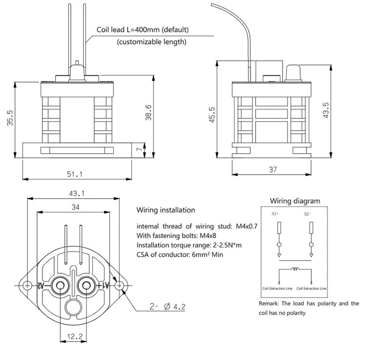
DC Contactor Relay Dimension
Notes:
1. When installing the DC contactor relay, a washer should be used to prevent the screw from loosening.
2. DC contactors with polarity shall be wired according to the marks on the product cover, there are no any requirements of incoming and outgoing lines for nonpolarity contactors.
3. Do not install the contactor in a strong magnetic field environment (near the transformer or magnet) or near the heat radiation source.
4. Do not use the contactor when its switching capacity and service life parameters are exceeded.
5. Make sure the working environment temperature between -40°C ~+85°C, too high temperature is easy to accelerate the diffusion of internal inert gas and it is necessary to avoid using the product under too high temperature environment.
6. When the resistive load is connected, it shall be used according to the rated parameters of the main contact. If the inductive load (L load) is connected and L/R > 1ms, the inductive load shall be connected in parallel with the surge current protection device.
7. During wiring and installation, to ensure that the main outgoing end and terminal head are clean and tightened to avoid excessive heating at the connection of outgoing end.

