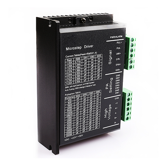
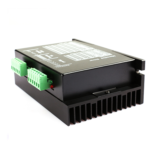


Digital Stepper Driver for Nema 16, 17, 23 Stepper Motor, 20-50V DC
- Stock: In Stock
- Model: PEACO-DSP57
- SKU: PEACO-DSP57
$99.85
Ex Tax: $99.85
Available Options
Free Shipping Worldwide.
By DHL/ FedEx/ UPS.
Lead Time 7-12 Days.
Mail Us for Lead Time of Custom Products.
MOQ 1.
Buy More Save More.
PEACO-DSP57 Digital stepper driver suits NEMA 19, 17, and 23 two-phase stepper motors and adopts 32 DSP technology, precision current control technology, vector control, advanced digital filtering technique, and anti-resonance technology. Our reliable stepping driver to drive a closed-loop hybrid stepper motor. Drive is widely used in textile machinery, CNC machines, printing equipment, etc.
Specification
| Model | PEACO-DSP57 |
| Subdivision Range | 400-25000ppr |
| Input Voltage Range | 20V-60V DC |
| Max Current | 4.2A |
| Signal Input | Differential/single end, pulse/direction or double pulse, 5-24V DC level compatible |
| Protection Functions | 200 KHz |
| Dimension | 151*97*48mm |
| Mounting Hole Distance | 143mm |
Pulse Signal
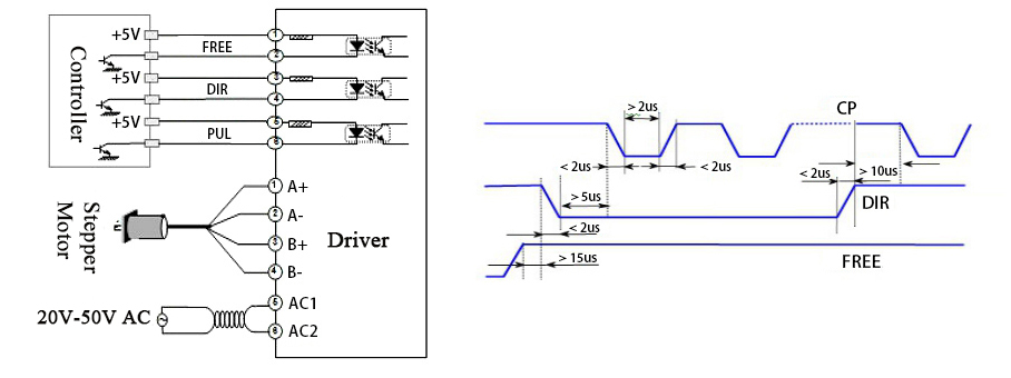
- PUL+ is the positive end of the pulse input pin, and PUL- is the negative end of the pulse input pin.
- DIR+ is the positive end of the direction input pin, and DIR- is the negative end of the direction input pin.
Enable Signal
- ENA+ is the positive end of the direction input pin. This signal is used to enable/disable the stepper motor driver. High level to enable the driver and a low level for disabling the driver.
- ENA- is the negative end of the direction input pin. Usually, it is unconnected (enabled).
Motor Interface
- A+ and A- are connected to the positive and negative ends of the A-phase winding of the stepper motor.
- B+ and B- are connected to the positive and negative ends of the B-phase winding of the stepper motor.
- When the windings of A and B are switched, the direction of the motor can be reversed.
Power Interface
- DC power supply, recommended operating voltage range: 20V-50VAC, power supply: >100W.
Indicator Lights
- The stepper motor driver has red and green indicators.
- The green indicator is the power indicator. When the motor driver is powered on, the green indicator is on.
- The red indicator is the fault indicator. When overvoltage or overcurrent faults occur, the fault indicator is on.
- After the fault is eliminated, the red light is off. When the stepper driver is faulty, you need to power it on and enable the stepper driver again to get rid of the fault.
Installation Instructions
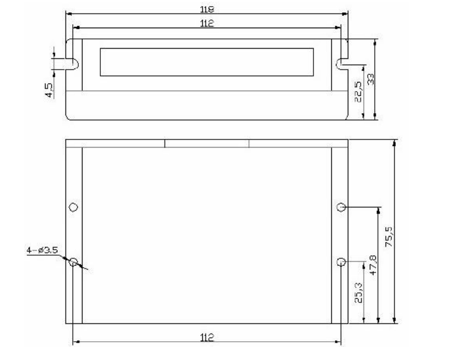
- The external dimension of the stepper motor driver is 118*75.5*34mm and the installation hole distance is 112mm.
- Both horizontal and vertical installation are available, but vertical installation is recommended. When installed, it should be close to the metal cabinet for heat dissipation.
Switch Options
| Output Current | SW1 | SW2 | SW3 |
| 1.00A | on | on | on |
| 1.46A | off | on | on |
| 1.91A | on | off | on |
| 2.37A | off | off | on |
| 3.48A | on | on | off |
| 3.31A | off | on | off |
| 3.76A | on | off | off |
| 4.2A | off | off | off |
Micro Step Selection
| PUL/REV | SW5 | SW6 | SW7 | SW8 |
| 400 | off | on | on | on |
| 800 | on | off | on | on |
| 1600 | off | off | on | on |
| 3200 | on | on | off | on |
| 6400 | off | on | off | on |
| 12800 | on | off | off | on |
| 25600 | off | off | off | on |
| 1000 | on | on | on | off |
| 2000 | off | on | on | off |
| 4000 | on | off | on | off |
| 5000 | off | off | on | off |
| 8000 | on | on | off | off |
| 10000 | off | on | off | off |
| 20000 | on | off | off | off |
| 25000 | off | off | off | off |
Notice: When the command input is not compatible with TTL, a series resistor for current limiting should be added at each signal input port according to the voltage level you use. Such as 24V with 2KΩ.
Stepper Motor Driver Installation Dimension (Unit: mm)

