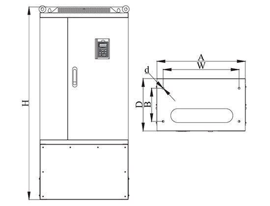


- Stock: In Stock
- Model: PEACO-FC280-4T-355G/400P
- SKU: TVFD-355400
Available Options
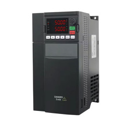
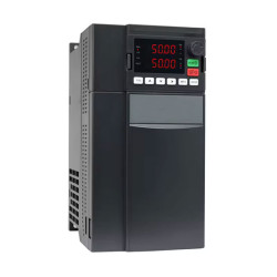
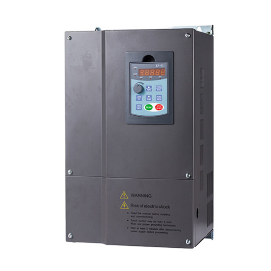
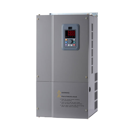
High-performance variable frequency drive (VFD) can drive and control motor speed to meet application requirements, 470 hp (355 kW) of rated capacity has a wide range of input & output voltages starting from 220V up to 660V, 1140V. Excellent vector control, durable design, and high start torque. Our all VFDs are tested with 24 hours aging test prior to supply.
Navigation: Motor Controls > Variable Frequency Drives > Three Phase VFD > 470 hp (355 kW) VFD, 3 Phase 380V, 690V Input/ Output
Specifications
| Basics | Model | PEACO-FC280-4T-355G/400P | |
| Rated Capacity | 470 hp (355 kW) | ||
| Rated Input Current | 665A (for 380V) | ||
| Rated Output Current | 650A (for 380V) | ||
| Certification | CE | ||
| Warranty | 12 months | ||
| Applicable Motor Output | 355 kW | ||
| Power | Input Rated Voltage* | 220V/380V/660V/1140V (-15%~+20%) & 460V/480V |
|
| Output Rated Voltage* | 220V/380V/660V/1140V (-15%~+20%) & 460V/480V |
||
| Rated Frequency | 1.0~3200Hz | ||
| Robust Design | IGBT current > 2 times of inverter output current, Capacitor > 50uF/A | ||
| PCB aging test | 100% test, 50°C, 12 hours. | ||
| Finished products aging test | 100% test, 50°C, 24 hours. | ||
| Control Feature | Control System | VF Control / Open Sensor Vector Control / Closed loop Vector (PG card) | |
| Output Frequency Resolution | 0.1Hz | ||
| Torque Characteristics | Including the auto-torque, auto-slip compensation, starting torque can be 0.5 Hz/150% (V/f), 1 Hz/150% (SVC),0 Hz/180% (FVC) | ||
| Overload Endurance | 150% / 120s, 160% / 60s, 180% / 10s, 200% / 1s | ||
| Acc / Dec Time | 0.1~65000s. (can be set individually) | ||
| Torque Boost | Automatically torque boost, manually torque boost: 0.1%~30.0% | ||
| Stall Prevention Level | 20~200%, setting of Rated Current | ||
| Operating Feature | Input/Output Terminals | Keypad | Removable |
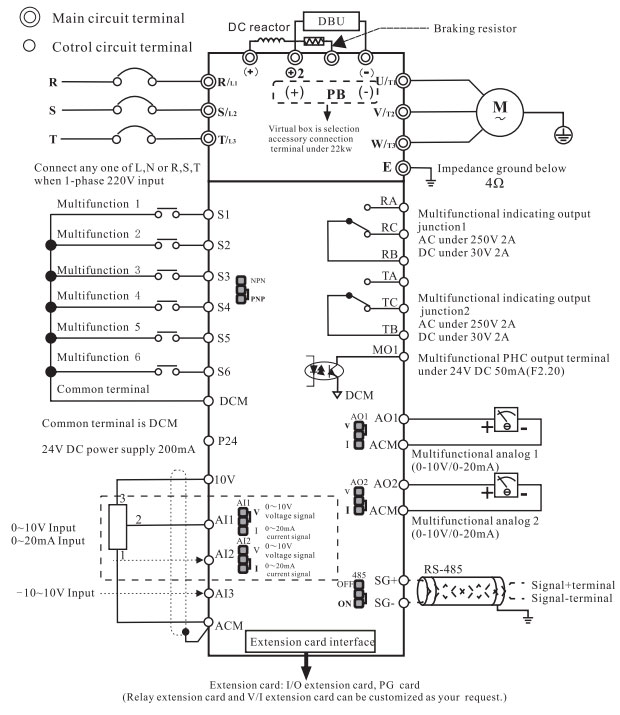
| Input terminals | 6 multifunctional inputs, one can work as high-speed pulse Input. 3 programmable analog input: AI1, AI2, AI3: 0~10V / 4~20mA. |
||
| Output terminals | 2 Groups relay outputs, 1 open collector outputs. 2 Analog outputs, 0~10V / 4~20mA. |
||
| Communication Terminals | Build-in standard RS485 communication interface. MODBUS-RTU communication protocol. | ||
| Built-in PID | Built-in PID control to easily realize the close loop control of the process parameters (such as pressure, temperature, flow, etc.) | ||
| Jog Operation | Jog operation frequency: 0.0Hz~maximum frequency. Jog acceleration/deceleration time: 0.1s~3600.0s. | ||
| Other Function | AVR, S-curve, Over-Voltage Stall Prevention, DC Braking, Fault Records, Adjustable Carried Frequency, Starting Frequency Setting of DC Braking, Over-Current Stall Prevention, Momentary Power Loss Restart, Reverse Inhibition, Frequency Limits, Parameter Lock/Reset. | ||
| Protection | Over Voltage, Over Current, Under Voltage, Overload, Electronic Thermal, Overheating, Self-testing. | ||
| Others | Including EMC Filter (C2/C3 Standard) | ||
| Cooling | Forced air-cooling | ||
| Installation | Altitude 1,000 m or below, keep from corrosive gasses, liquid, and dust. | ||
| Ambient Temp | -10°C~+40°C (Non-Condensing and not frozen) | ||
| Storage Temp | -20°C~+60°C | ||
| Ambient Humidity | Below 90% RH (non-condensing) | ||
| Vibration | 9.80665m/s2 (1G) less than 20Hz, 5.88m/s2 (0.6Gat) 20 to 50Hz | ||
| External Accessories |
Matched optional input EMC filter, output EMC filter, input AC reactor, output AC reactor, energy regenerated reactor, harmonic filter, and sine wave filter (excluding VFD price). |
||
VFD VS Frequency Converter
Variable frequency drive (VFD) is also called AC drive, a power control device that uses frequency conversion technology and microelectronics technology to control the AC motor by varying supply voltage and frequency. The main function of the VFD is to drive and control motor speed and torque and reduce the starting current to meet application requirements.
To generate variable voltage and frequency, VFD first converts the alternating current (AC) of the power source into direct current (DC), which is a process called rectification. However, an inverter converts direct current (DC) into alternating current (AC).
Generally speaking, the inverter converts the DC power supply into an inverter power supply with a certain frequency and voltage. The waveform output by the frequency converter is an analog sine wave, which is mainly used for speed control of three-phase asynchronous motors.
On the contrary, the frequency converter outputs a standard sine wave, which can vary the frequency, vary voltage, stabilize frequency, stabilize voltage, regulate frequency and voltage, and is mainly used in the testing equipment of instruments. The price of the frequency converter is 15-20 times that of the frequency converter.
- The first section of VFD (variable voltage control) not only converts the AC supply voltage into DC but also controls the required pulsating DC output voltage to maintain V/f constant ratio by using SCR/IGBT rectifier.
- The second section of VFD (DC-Link/DC Bus) consists of inductance and capacitors to convert pulsating DC into pure direct current. Here, inductance smooths the current, and the capacitor smooths the voltage.
- The third section of VFD (referred to as variable frequency control) not only converts DC voltage back into AC voltage but also controls the variable frequency to maintain the V/f ratio by using electronic devices such as SCR/IGBT transistors.
- Cooling method-forced air.
- Keep away the ac converter from corrosive gasses, liquid, moisture, and dust.
- Installation location altitude below 1000m (In the case above 1000m, VFD is to be de-rated. Please contact for technical support).
- Storage-temperate -20℃ to +60℃.
- Ambient temperature -10℃ to +40℃ (non-condensing and not frozen).
- Ambient humidity below 90% RH.
- Vibration under 20Hz 9.8m/s(1G), over 20Hz 5.88m/s (0.6G).
- V/f (volts per hertz) or V/hz control.
- V/f with encoder or closed loop V/f (PG card).
- Open loop vector control.
- Closed loop vector control (PG card).
- VFD capacity is to be sized more or equal to the sum of the capacity of all connected motors.
- The sum of the distance between the VFD and all connected motors should be less than 500m. Introduce an output load reactor to avoid motor failure due to voltage spikes, current surges, or harmonics.
- Install circuit breaker MCB or with extra protection MPCB between each motor and VFD.
- The voltage of each motor should be the same and ensure the VFD adoptable current is higher than the sum of all rated currents.
- Connect all motors with VFD output in parallel.

