

Single Phase SCR Power Regulator, 30A-150A
- Stock: In Stock
- Model: PEACO-TH-1-4-030-P
- SKU: PEACO-HQ-TH3
$378.98
Ex Tax: $378.98
Available Options
Free Shipping Worldwide.
By DHL/ FedEx/ UPS.
Lead Time 7-12 Days.
Mail Us for Lead Time of Custom Products.
MOQ 1.
Buy More Save More.
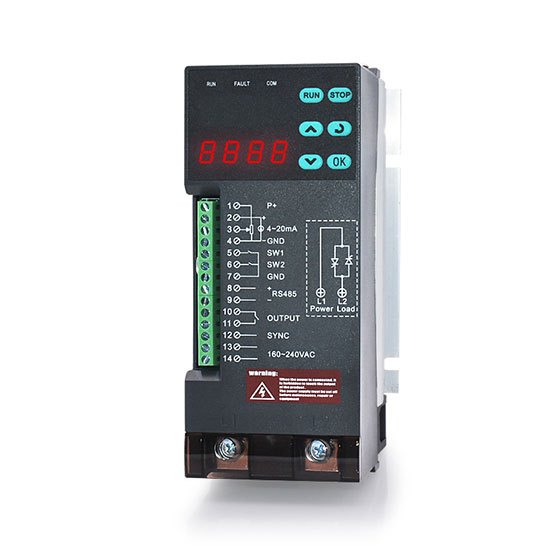
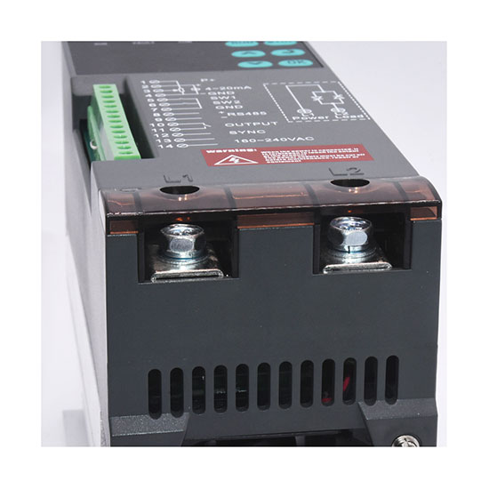
Single phase SCR power regulator can also be called voltage regulator / SCR power controller, comes with load simulation LED indicator lights, 30A to 150A optional rated current and 220V rated voltage. Control input signals can be 4-20mA, 0-20mA, 0-5VDC, 0-10VDC. High-efficiency power controller for electric heating high-temperature boiler, glass toughening furnace, powder metallurgy equipment and other industrial equipment.
For the user manual of the single-phase power regulator, please contact us.
Technical Specifications
| Power Regulator Model* | PEACO-TH-1-4-030-P ~ PEACO-TH-1-4-150-P |
| Analog input | Current input: 4-20mA/ 0-20mA |
| Voltage input: 0-5VDC/ 0-10VDC | |
| Main loop power supply |
Single phase 110V~220V, 50Hz/ 60Hz |
| Single phase 330V~440V, 50Hz/ 60Hz | |
| Control power supply |
AC160~240V |
| Output Voltage | The input voltage of the main loop is 0~98% |
| Output Current* | 30A~150A |
| Material | Aluminum alloys and plastics |
| Operation Environment | Temperature: 0~40℃, humidity: ≤90%RH (no frost) |
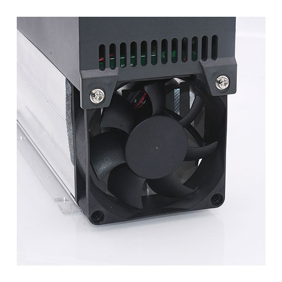
| Cooling Mode | Forced air cooling |
| Screws | M6 |
| Locking Torque | 40kgfcm |
| Certification | CE |
| Warranty | 1 year |
| Dimension (L*W*H) |
185*80*128mm |
| Installation Dimension | 100*73mm |
| Weight | 1.2kg |
Features and Benefits
* The single-phase SCR power regulator adopts MCU microcontroller control technology, built-in PID closed-loop control, and provides 100% linear output.
* Digital display - display input, output, voltage, current, and power five parameters.
* Dual-channel signal input design, both current and voltage signal input.
* Various control methods: constant voltage, constant current, constant power, open loop, and cycle control.
* Multiple protection functions: phase loss, over-current, over-temperature, disconnection protection.
* MODBUS RTU communication, the upper computer can directly control the output size.
Model Selection Table
| Model* | Current | Load Power | |
| 220V | 380V | ||
| PEACO-TH-1-4-030-P | 30A | 5.2kW | 9.1kW |
| PEACO-TH-1-4-040-P | 40A | 7.0kW | 12.1kW |
| PEACO-TH-1-4-050-P | 50A | 8.8kW | 15.2kW |
| PEACO-TH-1-4-060-P | 60A | 10.5kW | 18.2kW |
| PEACO-TH-1-4-075-P | 75A | 13.2kW | 22.8kW |
| PEACO-TH-1-4-080-P | 80A | 14.0kW | 24.3kW |
| PEACO-TH-1-4-090-P | 90A | 15.8kW | 27.3kW |
| PEACO-TH-1-4-100-P | 100A | 17.6kW | 30.4kW |
| PEACO-TH-1-4-125-P | 125A | 22.0kW | 38.0kW |
| PEACO-TH-1-4-150-P | 150A | 26.4kW | 45.6kW |
Note: * denotes optional parameters and you can select every parameter in drop-down lists to complete your order.
Current Calculation Formula
Single phase: SCR Current = 1.2*[(Load *1000)/Line Voltage]
Unit:
Current: A
Load: kW
Line Voltage: V
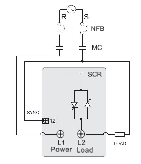
Main Loop Power Distribution
- NFB: The Power Supply can be cut off to avoid electric shock during repair and maintenance.
- MC: It can cut off the power supply to the load. When the power regulator fails or the temperature is too high, cut off the power to avoid burning the equipment.
- SCR: Adjust the output current according to the size of control signal to achieve the effect of temperature signal.
- Load: The load can be resistive load, inductive load, rheostat load, etc.
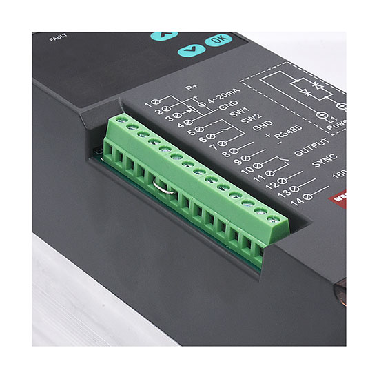
Control Terminal Function Description:
- P+ reference power supply +5V: A given reference for external potentiometers.
- A11 is the current analog input port 1: DC 0~20mA/DC 4~20mA (Input Impedance 125Ω) which forms input loop with GND.
- A12 is the voltage analog input port 2: 0~5V Input/potentiometer input (middle cap)/DC 0~10V which forms input loop with GND.
- GND is the Signal Common Ground for analog signal and switching signal terminal.
- SW1 is the external start/stop end. SW1 and 7 terminal GND constitutes start/stop, the regulator works when two terminals are closed and vice versa.
- SW2 is the external start/stop end with 7 terminal GND. If closed, select analog input port-2 if disconnected select analog input port-1.
- GND is the Signal Common Ground for analog signal and switching signal terminal.
- A is the RS485 Communication port +RS485.
- B is the RS485 Communication port -RS485.
- NO and COM Output relay to select a running output signal or alarm output signal, Load capacity AC240V/5A, DC24V/5A.
- SYNC is for power synchronization cable for details check main loop power distribution diagram.
- L, N is the control board power supply AC160-240V.

