
Generally speaking, capacitor compensation cabinets are installed in the power distribution room to improve the power factor. The contactor that controls the on and off of the capacitor is called the capacitor switching contactor, which is similar to the conventional contactor. However, there are some difference between them.
The contactors for capacitor switching is actually composed of a conventional contactor as well as extra auxiliary contacts and wires (resistance wires).
Function
The main function of the capacitor contactor lies in the auxiliary contact, which is very different from the conventional contact. The 33 and 34 contacts on the auxiliary contacts of the capacitor contactor have the same function as the conventional auxiliary contacts, which act together with the main contacts of the contactor. However, the functions of the three pairs of contacts on the left of the auxiliary contacts are different.
Auxiliary Contacts
The distance of the dynamic and static contacts of the three pairs of contacts beside the auxiliary contact is shorter than that of the contactor.
The initial state of the three pairs of contacts is normally open. When the contact coil is energized and the main contact is pulled in. Meanwhile, there is a sequential action. The moving and static contacts of the auxiliary contact are short, and the contactor is closed first, then the main contact is closed. When the main contact of the contactor is closed, the buckle structure on the auxiliary contact makes the auxiliary contact disconnected.
Summary
During the pull-in process of the contactor main contact, the auxiliary contact changes from normally open to normally closed and from normally closed to normally open. Namely, when the main contact of the contactor is closed to half, the auxiliary contact is closed. At last, when the main contact is fully closed, the auxiliary contact is disconnected.
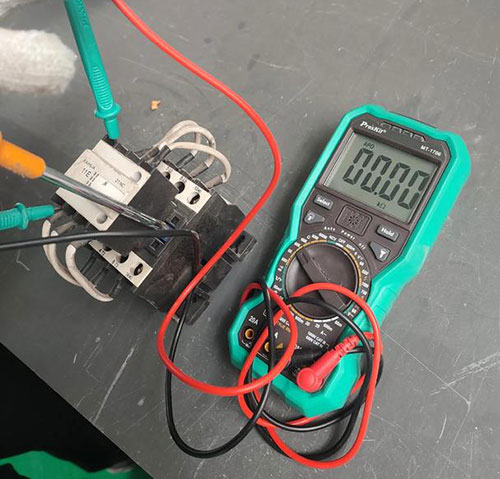
Use a screwdriver to press the main contact of the contactor to the half-closed position, and measure the auxiliary contact to be closed.

Use a screwdriver to press the main contact of the contactor, press it in place, you will hear a pop sound, the auxiliary contact is reset and the measurement auxiliary contact is disconnected.
Resistance Wires
The auxiliary contacts of the capacitor contactor are in a parallel relationship with the main contacts of the contactor. The wire used is not an ordinary wire, but a resistance wire. In other way, we can say that it is a resistance and the measured resistance value is about 1.
When the contactor is pulling in, the auxiliary contact is closed first, and the resistor is connected in series to the main circuit of the capacitor power supply, which is powered by the auxiliary contact and starts with voltage reduction. After the contactor is completely closed, the auxiliary contact is disconnected, the series resistance is cut off and the contactor's main contact supplies power to the capacitor.
The function of the capacitor contactor is to reduce the starting current by reducing the voltage of the series resistance. Although the contactor pull-in process only spends a few thousandths of a second, the auxiliary contact completes the step-down of the series resistance to start within the time.
The control method of the capacitor contactor is the same as that of the conventional AC contactor. The series resistance step-down start is completed by the auxiliary contact and the contactor mechanically, which is simpler and more convenient than the circuit control step-down.
Leave a Comment