
The brushless DC motor consists of a motor and a driver and is a typical mechatronic product. Brushless motor refers to a motor without brushes and commutators (or collector rings), also known as commutatorless motor. As early as the 19th century, the practical motor produced was the brushless motor, that is, the AC squirrel-cage asynchronous motor, which has been widely used in industrial field. However, asynchronous motors have many insurmountable defects, so that the motor technology develops slowly. In the middle of the last century, the transistor was generated, thus such a DC brushless motor that adopted the transistor commutation circuit instead of the brush and the commutator came into being. This brand-new brushless DC electric motor is also called an electronically commutated DC motor and technicists have overcome the shortcomings of the first generation of brushless motors.
This blog will introduce the brushless DC motor (BLDC), which is developing rapidly and widely used in daily utensils, automobile industry, aviation, consumer electronics, medical electronics, industrial automation and other devices and instruments. Addtionally, the mechanical commutation brushes are not adopted in BLDC instead of electronic commutators. Compared with the brushed motor, BLDC has many advantages.
Brushless DC Motor Structure
The brushless DC motor is a type of synchronous motor, which means that the speed of the motor rotor is affected by the speed of the rotating magnetic field of the motor stator as well as the number of rotor poles (p): n=60f/p.
In the case of fixed rotor pole number, the rotor speed can be changed when the frequency of the stator rotating magnetic field varies. The brushless DC motor is such a motor with a synchronous motor and an electronic control (driver) to control the frequency of the rotating magnetic field of the stator and feedback the rotational speed of the motor rotor to the control center for repeated correction in order to achieve the characteristics of the DC motor. In other words, the DC brushless motor can still control the motor rotor to maintain a certain speed when the load changes within the rated load range.
The brushless DC motor drive includes a power supply part and a control part. The power supply part provides three-phase power to the motor, while the control part converts the input power frequency according to the needs.
On one hand, the power supply can be directly input with direct current (usually 24V) or with alternating current (110V/220V). If the input is alternating current (AC), it should be converted into direct current by a converter first. Whether it is DC input or AC input, the DC voltage is supposed to be converted from the inverter to a 3-phase voltage to drive the motor before it is transferred to the motor coil.
The converter generally consists of 6 power transistors (upper arm: q1, q3, q5 and lower arm: q2, q4, q6) connected to the motor as a switch that controls the flow through the motor coil.
On the other hand, the control unit provides PWM (Pulse Width Modulation) to determine the switching frequency of the power transistor and the timing of the inverter commutation. Brushless DC motors are generally expected to be used for speed control where the speed can be stabilized at the set value without changing too much when the load changes. Therefore, the brushless motor is equipped with a Hall sensor that can induce a magnetic field as a closed-loop control of the speed. What's more, it is also used as the basis for phase sequence control. However, this is only used for speed control and not for positioning control.
1. Stator
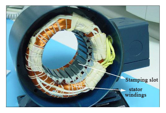
The BLDC stator is made of many silicon steel sheets which are laminated and pressed axially and each stamping slot has a certain coil to form the winding, which is shown as the following figure. Traditionally, the stator of a BLDC is a little bit similar to that of an induction motor. However, there are some differences in the distribution of the stator windings. Most BLDC stators have 3 windings arranged in a star row, each of which is composed of many steel sheets combined with each other in a certain way and an even number of windings are distributed around the stator to form an even number of magnetic poles.
The stator windings of BLDC have two types: trapezoidal and sinusoidal windings. The fundamental difference between them is that the back electromotive force generated by them is different due to the different connection methods of the windings, which show trapezoidal and sinusoidal waveforms respectively. The waveforms of the back EMF generated by the both windings are shown in the figure below.
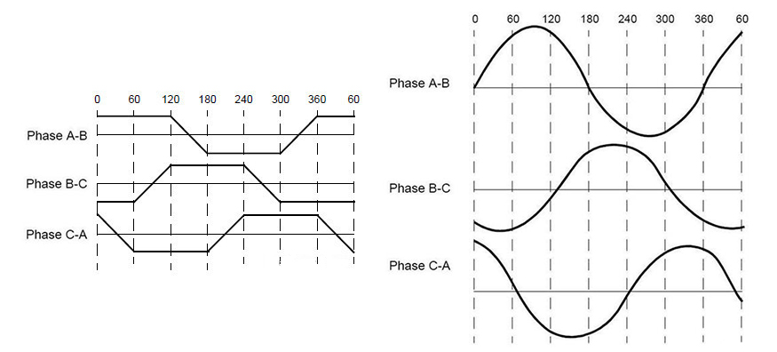
Figure 2: Waveforms of the Back EMF
In addition, it is necessary to explain the back EMF that the phase currents of the different windings also show trapezoidal and sinusoidal waveforms. It is conceivable that the sinusoidal windings run more smoothly than the trapezoidal windings because the sinusoidal windings feature smooth waveform. However, there is an additional cost, because the distribution of the coils on the circumference of the stator in a sinusoidal motor results in additional interconnections between the windings, which increases copper consumption.
Because there are different application voltages, users can choose brushless motors with different voltage ranges according to needs. Brushless DC motors with voltages of 48V and below can be used in automobiles, robots, small robotic arms, etc. Besides, such a brushless DC electric motors with the voltage range of 100V and above can be used in special appliances, automatic control and industrial production fields.
2. Rotor
The stator is composed of 2 to 8 pairs of permanent magnets arranged alternately around the rotor according to N and S poles (inner rotor type). If it is an outer rotor type BLDC, it is attached to the inner wall of the rotor as shown in the following figure.
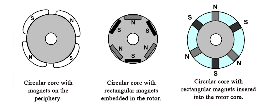
Figure 3: Magnetic Pole Arrangement of Rotor
3. Hall sensors
Compared with brushed DC motors, the commutation of BLDC motors is electronically controlled. To make a BLDC motor run, the stator windings should be energized in a certain sequence. It is important to know the rotor position in order to determine which winding will be energized in the energization sequence. The position of the rotor is detected by Hall sensors which are embedded in the stator.
Most brushless DC motors have three Hall sensors embedded in the stator on their non-drive end. Whenever the rotor poles pass near the Hall sensor, they emit a high or low signal, indicating that the magnetic north or south pole is passing the sensor. Based on the combination of these three Hall sensor signals, the precise sequence of commutation can be determined.
Hall effect: A magnetic field exerts a force perpendicular to the direction of movement of charge carriers in a charged conductor, which causes positive and negative charges to accumulate on both sides of the conductor respectively, which is especially noticeable in thin and flat conductors. The accumulation of charge on both sides of the conductor balances the effects of the magnetic field, creating a stable potential difference across the conductor. In a word, the process of creating this potential difference is called the Hall effect, which was discovered by E. H. Hall in 1879.
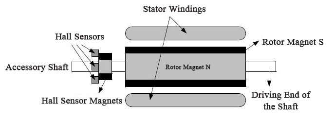
Figure 4: Hall Sensor Measurement Principle
Figure 4 shows a cross-section of a BLDC motor with a rotor with alternating north and south permanent magnet poles. Hall sensors are embedded in the stationary part of the motor. it is complicated to place the Hall sensors into the stator of the brushless DC motor, because any slight misalignment of these Hall sensors relative to the rotor magnets can cause errors in judging the rotor position. To simplify the process of installing Hall sensors in the stator, some motors may have Hall sensor magnets on the rotor in addition to the main rotor magnets, which are smaller in size than the rotor magnets. Whenever the rotor turns, the Hall sensor magnets have the same effect as the main magnets. The hall sensor is usually mounted on the PCB circuit board and fixed on the housing cover of the non-driving end, which, as a result, allows the user to adjust all Hall sensors easily to align with the rotor magnets for optimum performance.
In terms of the arrangement of the positions of the Hall sensors, there are 60 angle and 120 angle. Based on this arrangement, the current commutation sequence of BLDC motor is formulated by the manufacturer and this commutation sequence is required when users control the motor.
Note: The voltage range of the Hall sensors varies from 4V to 24V and the current range varies from 5mA to 15mA. Therefore, the current and voltage requirements of the Hall sensor should be considered when the controller is used. In addition, the output collector of hall element is open, and a pull resistor is required for use.
Leave a Comment